The use case diagram in Unified Modeling Language
The use case diagram is a behavioral diagram in the Unified Modeling Language (UML) which is used to depict object-oriented programming systems, and processes as well as business processes. UML is not a programming language but a modeling language. It is a standardized method for describing a planned or established system. This method uses diagrams in which all objects involved are structured and placed in relation to one another.
- Simple registration
- Premium TLDs at great prices
- 24/7 personal consultant included
- Free privacy protection for eligible domains
The use case diagram: one of many UML diagrams
Since it would be too complicated and confusing to depict all objects, relationships and processes in a single diagram, UML uses 14 different types of diagrams. They can be divided into categories: structural diagrams, behavioral diagrams, and interaction diagrams with interaction diagrams being a subset of behavioral diagrams.
Structural diagrams focus on depicting all elements in a system and their relationship to each other. A common example of this is the class diagram which can be used to group elements and visualize hierarchies. In contrast, behavioral diagrams do not focus on static structures. Instead, they show the planned or actual flow of processes that can be expected when using the program or software. These are dynamic diagrams.
The use case diagram is a special case within this group, since it depicts what behavior is expected from a system or software program in a specific use case. In comparison to other behavioral diagrams in UML, the use case diagram is quite static as it can only be used to describe the action and goal but not the exact sequence of the various workflows and actions. Other UML diagram types are used for this purpose, such as activity diagrams used to chronologically depict workflows and sequence diagrams used to show the exchange of messages between different elements in a system.
The use case diagram in practice
A use case diagram is used to depict a system’s functions from the user’s perspective (referred to as the “actor” in UML). The actor does not necessarily need to be a human user. This role can also be assigned to an external system which accesses another system. The use case diagram depicts the relationship between an actor and their requirements or expectations of the system without describing the actions taking place or putting them in a logical order.
In practice, this structure is useful for clearly depicting the most important functions and/or goals of a system. Therefore, when developing software or planning a new business process, one of the first steps is often to create a use case diagram. This diagram provides a simple and clear visualization of which use cases should be considered during development so that the actors (and more generally the users and clients) achieve their objective - this is initially considered without regard to technical feasibility.
Building blocks and structure of the use case diagram
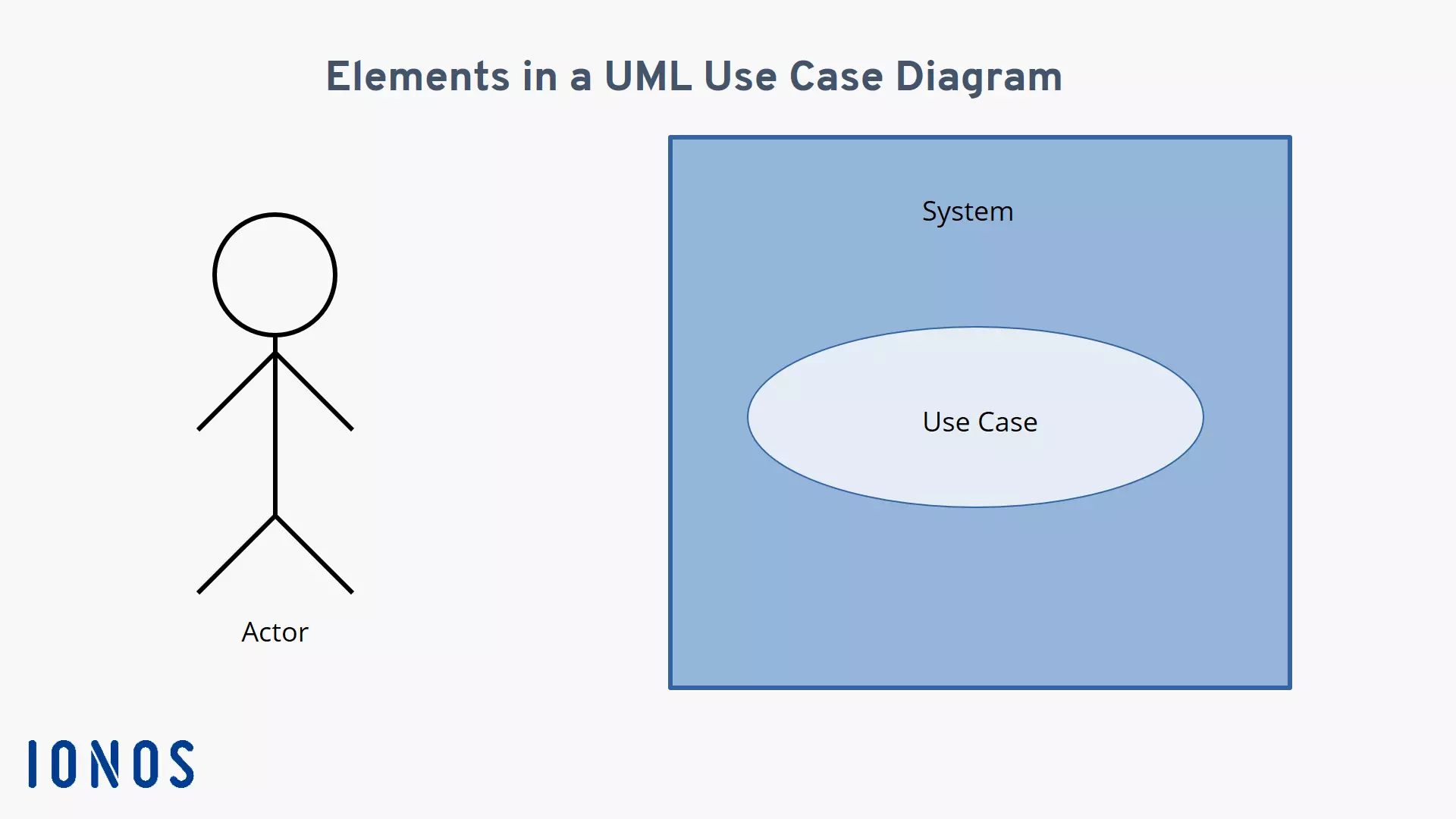
To ensure that everyone can immediately understand a use case diagram, standardized building blocks are used for the illustration. There are three essential elements to this:
- Actor: Actors, both persons and systems, are depicted as stick figures.
- System: The system being addressed by the use case diagram is depicted as a rectangle.
- Use case: A use case is depicted as an oval shape which usually contains a short phrase describing the process.
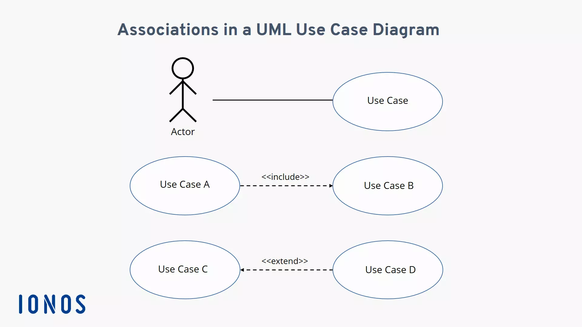
The relationships between these elements are described using lines to link them. These are called associations. A solid line between an actor and a use case indicates that the actor and the use case described in the oval are related. Dashed lines are used for relationships between different use cases. Since there are two different types of associations that can exist between use cases, the lines are expanded upon using a keyword referred to as a stereotype in UML which is enclosed in double chevrons. An arrow is also used to indicate the dependency between the two use cases. There are two distinct stereotypes:
- Include associations: This type of association means that a base use case includes a second use case. This is indicated using a dashed line connecting the two use cases with an arrow pointing toward the second use case.
- Extend associations: This type of association has a dashed line with an arrow pointing in the opposite direction towards the base use case. This means that the second use case extends the base use case under certain conditions, but it does not always happen.
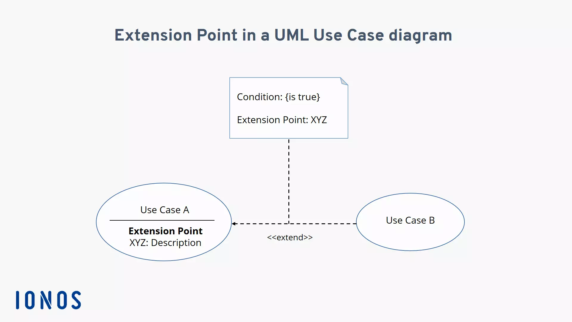
So, while the associations require that both use cases be executed, the second use case in the extend association is only executed under certain conditions. These conditions are specified in the UML use case diagram as extension points. This is illustrated in two ways:
- Extending the use case oval: Under the name of the use case, the possible extension points are named and briefly described.
- Adding a note: The extended stereotype is connected via a dashed line to a stylized note (i.e. a rectangle with a bent corner) which is labeled with “condition” and “extension point”. Next to “condition” enclosed in curly brackets, you will find the condition which must be met for the second use case to be executed. Next to “extension point”, you will find the name of the use case oval so that the extension can be clearly identified.
You now have all the building blocks required to create your own use case diagram.
An example of how to create a use case diagram
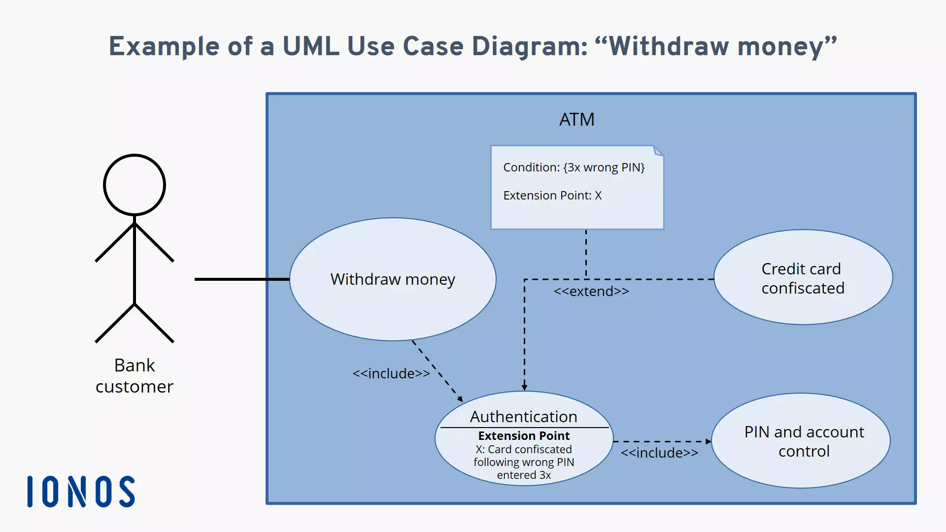
Up to this point, we have presented a lot of theoretical information. To help you better understand the practical implementation of a use case diagram, we are going to go over how to create one using a bank customer who wants to withdraw money from an ATM as an example.
Always ensure that your use case diagram does not become too confusing. This can happen quickly if you try to depict several use cases in the same diagram which are also connected by <<include>> and <<extend>> relationships. When in doubt, it is better to create a separate use case diagram for each use case.
In this example, the ATM is the system and the bank customer is the actor intending to execute the “withdraw money” use case. This use case is connected through dependencies to two other additional use cases: “authentication” and “PIN and account verification”. If the authentication is not successful, the customer’s request cannot be executed. To prevent the customer from making an infinite number of attempts, the card should be blocked after the PIN has been incorrectly entered three times. Therefore, an extension point is added to the “authentication” use case with the condition “incorrectly enter PIN three times”. If this condition is met, the “block card” use case is executed which is connected to the “authentication” use case via an extend relationship. Here is what the use case diagram for this example looks like:


